Introduction
I've recently reverse engineered the USB protocol used by certain Beijing JCZ fibre laser controllers, and developed command-line tools to control them, suitable for tech-savvy users and OEMs wishing to integrate these commodity lasers into larger systems where the Windows-based GUI "EzCAD2" software they typically come with would be an impediment.
Background
Fibre lasers have revolutionized the solid state laser space in the past decade. Using a doped optical fibre as the gain medium, they overcome a major difficulty with solid state lasers: heat dissipation. The high surface area to volume ratio of the extremely long fibre allows heat to escape the medium easily compared to a thick rod or disk. Fibre lasers are still relatively expensive, but they have come down in price to the sub-$1k range at the low end for a 20W average power, Q-switched near-IR module.
Some vendors combine a pulsed fiber laser module with a galvanometer scanner and lens to produce a high-speed laser engraver capable of marking on (and sometimes even engraving or cutting) metals and ceramics. On some materials, by configuring the cutting speed, pulse power and frequency, different colors can even be produced. One interesting application is isolation routing of circuit board prototypes. Frequency doubled (532nm, green) or tripled (355nm, near UV) pulsed Nd:YAG lasers have been used commercially for this, but it's a misconception that near-IR lasers can't machine copper: with a high instantaneous power, they definitely can, though judicious configuration is required to avoid burning PCB base material. (It is another misconception that lightly burned FR4 is conductive: on the contrary, experiments reveal that although it is visibly darkened, resistance across a fifty micron gap exceeds the 5.5 gigaohm maximum of my megger at 500V.)
Since even the most inexpensive galvo scanner fibre laser engravers can hold 0.1mm features, and are able to remove copper, cut the board material and drill vias in a single operation, they are an attractive prospect for rapid PCB prototyping. (They can also remove soldermask material, leaving only through-hole plating and surface finish to be done by chemical means, neither of which require additional masking.) Unfortunately, the missing link up to now has been the software: the inexpensive galvo scanner fibre laser engravers are provided only with the Ezcad2 software, which is a proprietary program that only runs on Windows and has no features to support PCB manufacture - it doesn't even have a fully working SVG importer.
Reverse Engineering and Technical Details
I obtained a fibre laser engraver, the cheapest new one on eBay, for about $2300 in October of 2021. (Prices have been declining over the past few years.) It is purportedly "YOURBONGER" brand, which is a trademark of Shanghai Zeyi Machinery Equipment Co. Ltd. However, it has no brand markings on the outside, and there are many similar looking machines available from different vendors.
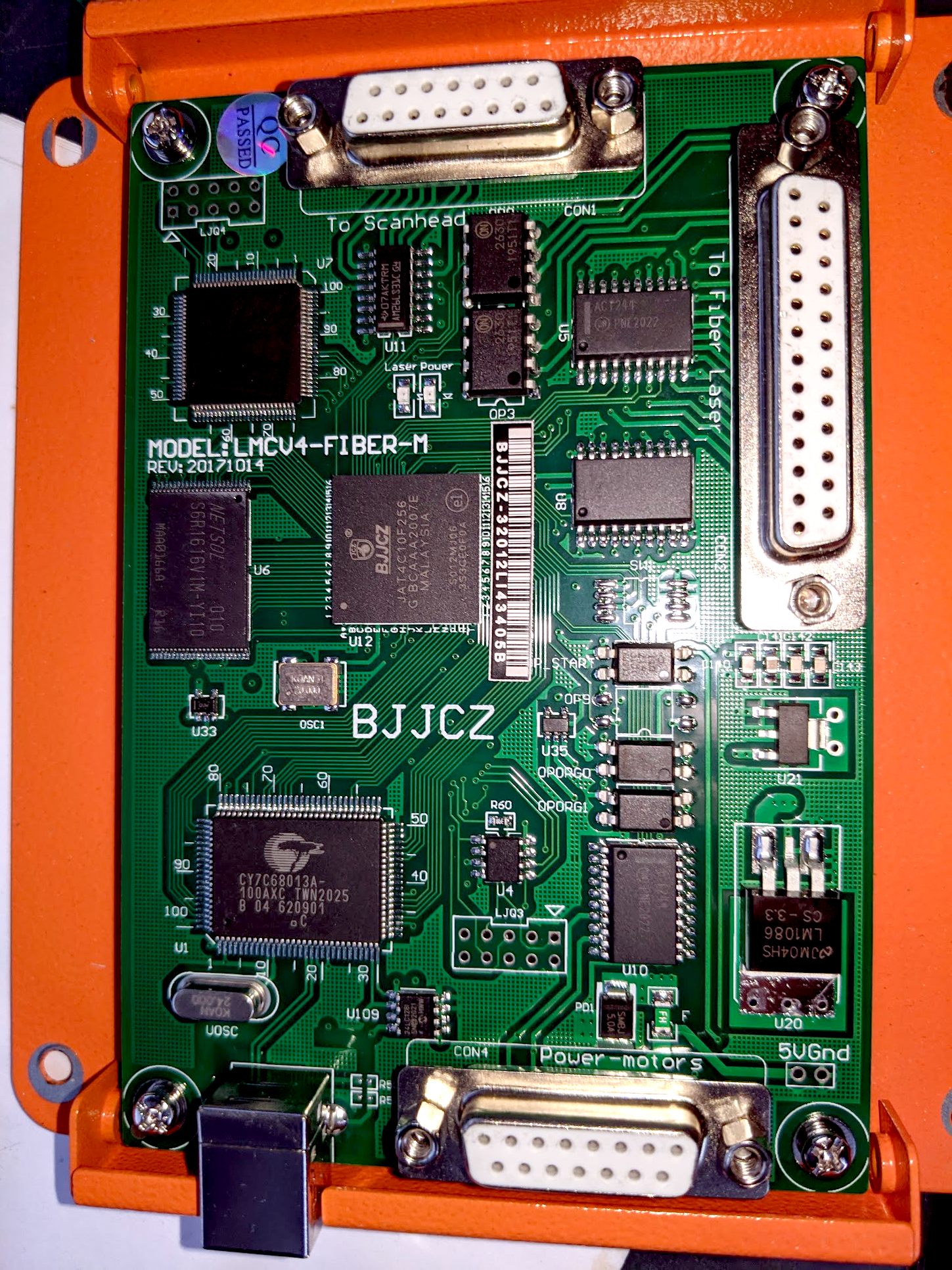
My machine has a 20W Raycus laser source (RFL-P20QS) and Beijing JCZ LMCV4-FIBER-M control board, revision 20171014. Some similar machines may have Max Photonics sources (another Chinese brand); more expensive machines sometimes have JPT laser sources. A picture of the board is on the right. The board is based around an Altera FPGA and a Cypress modernized 8051 USB microcontroller. (Note that the FPGA has proprietary markings for Beijing JCZ; somehow I am not shocked that a company that makes laser marking machine parts has managed this.)
On the board you can also see that it is provided with a fairly large RAM chip for buffering and presumably an EEPROM near the unpopulated header to load the configuration of the FPGA. The board talks an openly described protocol XY2-100 to the galvo scanner head, and can also control a rotational axis with a stepper motor (though mine doesn't have this feature.)
I haven't at this point bothered to try to get the firmware of the microcontroller or FPGA configuration; it doesn't seem to be necessary to answer any outstanding questions I have after black-box reverse engineering it using USB packet capture. The general approach I used was to do various operations in EzCAD2 while observing the USB packet traffic, then playing back the data with modification until the protocol was reasonably well understood.
The machine presents three USB endpoints; one is used to send commands to the engraver via USB BULK transfers, the other is used to poll the engraver machine's status, and the third is a security dongle that EzCAD2 polls as an attempt to prevent cloned boards from working with EzCAD2. The dongle interaction that EzCAD does is very time consuming and accounts for a substantial part of its slow startup! Fortunately, the engraver machine does not care if the dongle interaction is done or not, and it can be skipped for a substantial savings in time.
Commands are sent to the machine in bunches of 256. The commands (movement, laser parameter configuration, etc) are all 12 bytes long and the bunch is padded out with no-operation commands if there are fewer than 256. A simple protocol governs whether or not the machine is ready to get more commands or not, and whether or not it is still busy executing the commands already loaded into its buffer. During idle periods as well as operation, EzCAD keeps up a lively discourse with the machine, polling it every few milliseconds (presumably so it can monitor the state of interlocks and the footswitch.) However, to do so is not necessary unless one is using these features.
Please see the code (to be discussed below) for additional information on how the protocol works. Note that there are many kinds of these boards and I have only examined one example at this point! Submissions of pcap files from technically sophisticated users with different lasers would be appreciated. I have also heard rumors of cloned BJJCZ control boards that only work with one particular version of EzCAD (presumably due to imperfect dongle emulation) - I would certainly like data from these boards as well since they represent a different implementation of the protocol and third-party computer-side control software would represent a particular boon to them.
Installation of Balor and Calibration
I've named my laser engraver control software "Balor" after the king of the Fomorians, Balor, a giant with a huge eye that destroyed things he looked at with it, which seemed apt to me. I've divided my control software into several parts:
- balor-test: generate test patterns, e.g. for calibration.
- balor-debug: turn machine code into images or command-by-command descriptions.
- balor-raster: create machine code from raster images (e.g. PNG files.)
- balor-svg: create machine code from a restricted subset of SVG files.
- balor-ngc: create machine code from a subset of g-code.
balor: send machine code to an attached engraving machine.- balor-sender: send machine code to an attached engraving machine.
These programs are licensed under the GNU GPL, Version 3, or at your option, any later version. See the license file in the source code directory. If you want to include parts of this code in your proprietary program, please contact bryce@gnosticinstruments.com to arrange commercial licensing and/or support; Gnostic Instruments is available for adding BJJCZ fiber laser support to your existing software on a contract basis. Balor is copyright 2021 Gnostic Instruments, Inc.
The Radial Basis Function interpolator provided with balor is separately licensed under a permissive license and is part of very recent versions of SciPy; I included it separately because of its scarcity in the wild at the present time. It is Copyright (c) 2001-2002 Enthought, Inc. 2003-2019, SciPy Developers. All rights reserved.
To make use of any of these, you'll need to Download from GitLab. I used pyusb for the user-space USB protocol implementation, which is cross-platform, but I have not used this on Mac or Windows yet and reports about compatibility problems are desired. Other dependencies include numpy, scipy, Pillow / PIL (for balor-raster), svgpathtools (for balor-svg), and gcodeparser (for balor-ngc).
Remember, all of this is experimental. It may not work with your engraver: there are many kinds of BJJCZ galvo laser control boards. I have put photographs of my machine's controller in this directory. If your board doesn't have the same model number, and maybe possibly revision, it may well not work. This software is, again, EXPERIMENTAL. It may contain serious bugs that will damage your machine or ruin your workpiece. Accordingly, there is no warranty. See the license file in the main directory. Lasers are dangerous and can set things on fire or blind you. The beam from the laser cutter is focused but its specular reflection can absolutely damage your vision under optically unfavorable circumstances. If you're using one of these machines, please take appropriate precautions. 1064 nm light is completely invisible and vision loss to lasers is insidious. Also, while a q-switched or MOPA laser usually prefers to disintegrate things, with the right (wrong) settings it can totally set them on fire, too. Disintegrated things probably shouldn't be inhaled. Fume extraction would be good especially if you are going to mark plastic as the calibration section below will suggest.
Please be sure to read the explanatory text rather than just pasting the commands in blindly and hoping for the best. READ IT ALL. Google the things you don't know what they are. Look at the source code. If after doing those things you still don't understand, please ask me for help: bryce@gnosticinstruments.com In the rest of this document, I will convince you that I am not a technical writer, but I will try to help you, my time and interest permitting. Support requests that provide pcap files (see below) and pictures of the control board similar to the ones I have provided for my machine will be prioritized. There is also a support forum now at Maker Forums.
You should probably do some captures of your laser engraver talking to Ezcad2 to make sure that the protocol at least looks the same. An example file, ThreeOvals.pcap, is provided so you can see what it looks like when my machine starts up and engraves three ovals. You can capture USB traffic with wireshark: See here: https://wiki.wireshark.org/CaptureSetup/USB If your laser does not produce similar-looking traffic, please let me know. I'd appreciate also having a photograph of the board and any serial numbers or marks that may distinguish it.
In principle, Balor is cross-platform. It uses a user-space USB driver with libusb. On GNU/Linux, it should just work, providing of course that you have a working pyusb installed (left as an exercise to the reader.) The program might not work if you are not root. You will need to correctly configure udev rules and user groups so that this is not necessary. My laser has USB vendor ID 0x9588 and product ID 0x9899. You can also just run it as root if you want, I'm not going to judge you.
On Windows, you will need to install pyusb and a backend for it, such as libusb, along with its generic driver. Then, use something called Zadig to associate the generic USB driver with the laser engraver instead of the proprietary driver that comes with Ezcad2.
On Mac OS... I don't have any idea, but PyUSB is supposed to work on it and I suppose it would be like Linux above otherwise.
Having installed the software, you will need to calibrate your machine (and lens) for best results. An example calibration file is included with the software, but it's one that I made with my machine (with the nominal 150mm lens) and it will probably be wrong for your machine, grossly wrong if you have a different lens. The calibration file, essentially, establishes a relationship between millimeters (or some other unit, in principle, but I made balor with the assumption that the unit will be millimeters and so using other units will expose issues) and unscaled "galvo units."
The machine uses internal coordinates which are 16-bit integers for its movements. Depending on what lens you have on your engraver, each "galvo unit" as I call it will correspond to a different distance. For example, if you have a 150mm working area machine, the galvo unit is about 2.3 microns of distance. Key word is "about." This is very approximate. First, it is notably different in the X and Y dimensions, by about 10%. Second, it is different depending on where you are in the working area. The distortion is, essentially, "barrel distortion", the opposite of pincushion distortion. The machine seems to have some degree of distortion correction built in, and a table for this is loaded when the machine starts up. This software, as it comes to you, does not include the table; it is a .cor file that may have come with your EzCAD installation and is produced by the program CorFile2.exe if it did not. (Support for making corfiles without needing an external program is pending.)
In any case, however, the corfile is not good enough; it does not completely linearize the relation between galvo units and distance. So, this software uses a second calibration based on the radial basis function. A file, cal_0002.csv, contains calibration data to calibrate my laser to real units and compensate for the remaining distortion. This calibration step should be able to compensate for any error that the corfile compensates for, as well, so in principle you don't need a corfile if you don't already have one.
The calfile (distinct from the corfile) is based on adial basis function interpolation. Get yourself a good set of calipers - you need those for the corfile too, if you're choosing to do a corfile. If you are doing a corfile, you should do that first and use it with balor-sender in all the subsequent steps. You will also need something flat that your laser can mark on. Ideally, it should be able to make a deep enough mark that you can feel it with the caliper jaws. I use Canon CLC transparency film. Instead of calipers, you can of course use a measuring microscope or other calibrated optical equipment.
Then you use the balor-test.py program to make a calibration grid pattern.
You're going to mark this pattern (using balor itself) onto your material and
then measure the coordinates of where the line intersections actually are
relative to galvo 0x8000,0x8000 (the center position.)
Make a copy of cal_0002.csv and use it as a template.
This is the invocation to mark the grid (omit -c mycorfile.cor if you have no corfile):
./balor-test.py mark -t grid | ./balor-sender.py -c mycorfile.cor
(You should probably have verified that your laser works with balor
well enough to light a pattern with the guide laser first.)
The result should be a grid with an X in the center. The intersection of
the lines of the X is the zero point of your laser. Use the calipers to
measure the distances of the points along the X and Y axes, then measure from
the axes to every other line intersection and thereby fill out cal_0002.csv.
Have fun with that. Note, so as to avoid getting confused, a small right
triangle is drawn to mark the +x, +y direction of your laser. The 90 degree
corner of the triangle is nearest the y axis. Probably label them and add
labels (with a marker or whatever) to all the lines, so you don't get confused.
You will probably get confused anyway, so you can use the script view_cal.py
to check how often you got confused while making all those measurements:
./scripts/view_cal.py cal_0002.csv
You should see something approximating barrel distortion. Look for outliers
that probably represent some kind of gross error (getting confused about axes,
signs, etc).
Having obtained your calibration file, you can then supply it to balor's generators (balor-test, balor-raster, balor-vector) so you can use millimeters instead of galvo units (calibration) and maintain that relation regardless of where in the field you are engraving (compensation). I guess, if you wanted to use some other units, e.g. cm, you could just use them consistently in the calibration file and ignore all the times my code just assumes it is mm and calls it mm. The galvo DACs don't care, yo.
You will probably want to try out your shiny new calibration file.
./balor-test.py mark -t cal --calfile cal_0002.csv | ./balor-sender.py -c mycorfile.cor
Once again, the corfile is optional. (I will omit the optional corfile in subsequent examples,
but it's something you can provide to balor-sender and if you used it making your calfile,
you subsequently have to always use it.)
This will make a grid of 1 cm squares inside a big crossed lines figure in
a box. Measure all the squares to make sure each one is 10.00 mm in width and
height, look at the intersection of the four lines to make sure they cross 0
at the same point, and make sure the sides of the outer box are straight and
perpendicular to each other.
The box marks the calibrated area of your laser using your new calfile. It will be somewhat smaller than the nominal size of your engraving area. balor-test provides various options for customizing the calibration pattern so you can calibrate a larger area if you like, though note that the distortion gets a bit wild outside of this area. The "good" area is really a circle rather than a square, though, so you can definitely go farther along the X and Y axes if you want. Note that if you do this stuff you will also need to change the calibration file accordingly (e.g. adding more data points or just changing the galvo unit coordinates corresponding to the measured points.)
The default settings for balor-test are for making nice visible lines on Canon CLC transparency film with my 20W q-switched 1064 nm laser. The power is always relative to maximum laser power, so if you have say a 50W laser you will probably fry the transparency film, or make unecessarily wide lines that will be more difficult to measure accurately. You can configure laser power, q switch frequency, and cutting speed with balor-test, run it with the -h option for an explanation of command line settings.
Balor test can also generate a grid lighting pattern, like this:
./balor-test.py light -t oldgrid -c 8192 | ./balor-sender.py
Be sure both the generator (balor-test) is set to "light"
mode.
As noted above, you may need to run balor with root permissions, e.g.
./balor-test.py light -t oldgrid -c 8192 | sudo ./balor-sender.py
In all this, you may want to preview an image before sending it to be marked or even
lighted. Balor comes with a debugging program that can produce a graphical output
approximating what the machine will produce. It's more like a plot of the
galvo movements than an actual preview. Grey lines are travels, green are cuts,
red are cuts made with the laser off (probably a bug in something.)
./balor-debug.py -f msbf-file.bin -o output.png
It will also produce text-mode output:
./balor-debug.py -f msbf-file.bin -o output.txt
Which will be a (probably long) text file explaining each command in the MSBF.
That's useful for debugging, maybe. Note that balor-debug doesn't take
calfiles into account, so if you used a calfile to produce the MSBF, you will
see distortion in the graphical plot produced by balor-debug. This is in fact
the correction necessary to compensate for the machine's distortion as
corrected for by the calfile. Balor-debug does not account for corfiles either,
it simulates an ideal machine.
Using Balor
All of these programs have a -h option to show help. The balor program proper also has a verbosity level switch which may be helpful in troubleshooting. I am not a technical writer and to be honest I am not trying my hardest here, I am putting this out there in the hope that other people will show up to help, both with the coding and documentation, which is what happened with the last open source project I launched. Here's hoping.
How to use balor-raster to engrave raster images
balor-raster engraves raster images. Currently, it only engraves with one set of laser settings and each point is either on or off. You can configure the threshold value and a form of very simple dithering is also available. However, there is nothing stopping you from doing a color separation manually in an image editor, doing halftones, etc.
Suppose you've got a greyscale or black and white image called
parrot-grey.png. First use balor-raster in light mode to show where it is
going to end up on your workpiece:
./balor-raster.py light -f parrot-grey.png -c cal_0002.csv -s 200 | ./balor-sender.py -r 0
The -r 0 means "loop until I terminate the program," which is often what you
want with lighting.
I prefer to generate the machine-specific binary format separately
rather than use a pipeline because it takes a long time (the RBF calculation is
computationally expensive and replacing it or just optimizing its use would be
fruitful.) Do like so:
./balor-raster.py mark -f parrot-grey.png --laser-power 40 --q-switch-frequency 40 --raster-x-res 0.1 --raster-y-res 0.1 -c cal_0002.csv -o parrot-g.bin -s 80.0 -t -0.5
And then run: ./balor-sender.py < parrot-g.bin
You will observe that there are a lot of settings there. Use balor-raster.py -h to give you the
quick rundown. You can preview the image with balor-debug.
How to use balor-svg to engrave vector images
SVG is a complicated format and includes many features that would greatly complicate balor-svg and many features that do not make sense for a laser engraver. Currently, balor-svg only supports engraving paths. Other SVG entities such as rectangles, ovals, and especially text, are ignored. Your SVG editor should include an option that is called something like "convert to path" which can be used to turn those objects into paths so they can be detected by balor-svg.
Your SVG editor may also be adding transformations, such as translation and rotation, do your object. balor-svg may someday honor these, but currently does not, so if your geometry is ending up inappropriately scaled, translated, or rotated, this is probably the result of balor-svg ignoring transforms. Your SVG editor should include an option for baking in transforms, or else you can edit the SVG file with a text editor to delete all transforms and then move the objects back to their intended place. In particular, Inkscape will create transforms on things if you resize the document after making geometry. Also, balor uses positive and negative coordinates, which Inkscape supports, but it draws the document outline as the +X, +Y. At the moment, if you want to use your full marking area, the simplest solution is to just treat the upper left corner of your document as the origin and put stuff on all sides of it.
Lighting mode example:
./balor-svg.py light -c cal_0002.csv -o light-cattag.bin -f examples/cattag.svg
Marking mode example:
./balor-svg.py mark -c cal_0002.csv -o cattag.bin -f examples/cattag.svg
As a reminder, you'd then mark the .bin file (or light it, whichever):
./balor-sender.py -f cattag.bin
Like the other balor converters, balor-svg will take options for laser parameters, cut speed, etc. However, these are only the defaults. balor-svg is able to use different parameters for paths of different colors. Since balor-svg ignores text, you can conveniently embed the parameters in the svg file itself as text beginning with the symbol !pen and then a color in hexidecimal and the laser settings. Any lines in that color will be marked using those settings. This will only work if your SVG editor saves colors as hexidecimal. If it does not, it won't work and you'll get default pen for everything. I only use Inkscape to edit SVGs so if yours doesn't work, send me some examples.
Besides embedding laser settings in the SVG file itself as text, you can also supply a settings file (.csv, space or tab separated, let me know if you need actual commas) separately instead.
Paths which are filled will be hatched by the machine using the laser settings corresponding to their color, as with lines. Currently, the hatch angle does not do anything yet, and only the default Hatch pattern (parallel lines) exists, but the program is architected to support other hatching patterns if they are needed. Hatch spacing is configurable already. It is in microns (micrometers, 10e-6 meters) rather than mm.
How to use balor-ngc to convert gcode
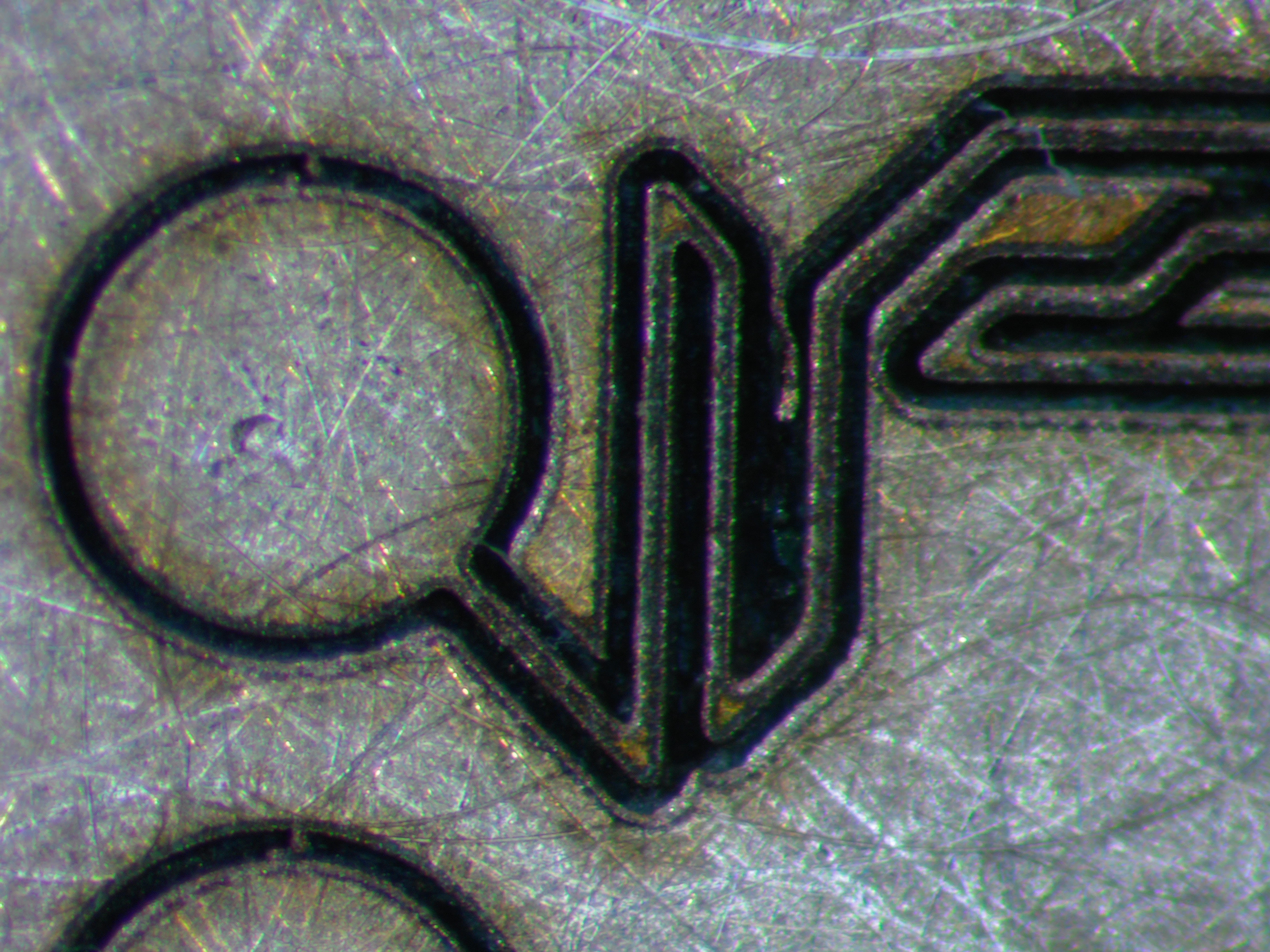
Last but certainly not least, balor can convert gcode to BJJCZ machine code, which allows you to use the output of CAM software, such as FlatCAM, to control your engraver. I have in fact at this point only tested it with FlatCAM. FlatCAM can make isolation milling gcode from GRBL files, which in turn can come from a PCB CAD program like KiCAD, so you can make your own circuit boards this way. This is not to be underestimated as a PCB making method for prototypes, because these lasers can hold the feature sizes you would get from a low-cost PCB prototyping service quite easily. In fact, with no especial effort, I've achieved 2 mil/thou features (50 micron) and trace separation, a level of resolution more associated with modern mobile phone PCBs than a dish of ferric chloride and an aquarium pump.
FlatCAM can also be configured to mill the holes in a PCB (distinct from drilling - milling is where you have one small bit and use it to make holes of various sizes larger than the milling bit, whereas with drilling you use multiple drills of various sizes to make the through-holes and vias of varying sizes.) balor-ngc can be used with gcode made by FlatCAM to mill (not drill) holes and cut the board edge / make perforations as well. It can also be used to selectively remove a solder mask after you've applied it to the whole board, though balor-svg might well be better suited for that sort of application.
Because you will generally get better results from multiple passes rather than slower
cutting (allowing heat to disappate rather than overheating the PCB material) the -r
option for multiple repetitions may be particularly useful for balor-ngc. Here
is an example of how to use FlatCAM-generated gcode to mark a PCB:
./balor-ngc.py mark -r 10 -c cal_0002.csv < examples/pcb/shifter/iso.gcode > iso.bin
Conclusion
Please get in touch with me if you would like to help with this project. In the coming few weeks I plan to upload a complete example of how to make a PCB with balor. Let me know of other sorts of examples you would like to see. I can be reached at bryce@gnosticinstruments.com. Thanks!
Demo: vector engraving on titanium.